As the project has now been completed, and a presentation prepared, an it is now a good place to sum up the experience.
The groups were assigned in week 1 after which minimal progress was made due to the creation of a 3d head. In this period of time a visit was made to the museum of power, and a short group meeting was arranged to decided from which of the models we should look into taking further.
The model was chosen, and research into it was made over the next few weeks. Once the 3d head had been created, all work switched to the model.
Within the group, we all found that we had different areas of expertise. In my case, I was best at animation, cameras, lighting, and as the member with the newest version of the software and the most power (64-Bit) rendering.
In agreement with the rest of the group we all worked on different areas, which in my situation, I worked on the wheel to go onto the model, followed by animating the model, adding in lights, and then finally rendering it.
Further tasks in addition to this set also included a further low key spinning version of the model, and also part of the final presentation.
During the work on this project I learned several new skills, firstly, how effective group work can be, when everyone knows their strengths and weakness. Also, i picked up several new skills regarding how to build models using proboolean effectivly, and in animation, with my extensive use of the curve editor tool with the animation.
As the group worked so effectively, we were left with plenty of time to render, which is why a 14 hour render did not cause any problems with our time scale. This gave us plenty of time to add in a narration track, and to edit the video footage in Premiere to make sure we had the files which we needed.
Later on small problems with the animations timing were discovered, and whilst it would be possible to fix the issue, because of its minor importance and low visibility as well as then extensive rendering time, it was decided that there would not be enough time or reason to go back almost 3 weeks to fix such a small issue.
Overall, I am pleased with both the work that we have outputted as a group with this project, and also I am pleased with the input to the model that I had, and that I learned new skills.
Monday, 7 December 2009
Wednesday, 2 December 2009
Another Render.
After creating the final product, a group decision was made that in order to make the presentation of the product to the client more enjoyable; that a untextured rotating un-animated version of the model needed to be created.
The meant opening a previous version, and then removing any animation from it in order to create a greyed out un-animated model.
To make the model rotate, once again, the curve editor was used. In this situation, the model was grouped, and key frames added for it at 0 degrees, 180 degrees and 359 degrees (the 1 degree missing is to avoid a slight delay caused by the same angle being used twice when looping). Then, using the curve editors out of range editor, a simple loop animation was created.
After an initial one frame render, it was decided that the model needed a little mor elighting, so a couple of omni lights were added. The intensity of these lights was too high initially, whoever once they were lowered to 0.4, it was about the right intensity. Shadows were then applied to one light using the advanced shadows setting.
The model was then rendered for 600 frames, giving 20 seconds of animation, which will then be looped for use in the presentation. Unlike the previous render, this version only took 35 minutes.

Monday, 23 November 2009
Lights, Camera, Action.
After combining the animated model with the environment, it was time to add lighting, cameras and to finally render the model. This was the final stage of work done in 3dsMax.
As the model is out in the open within the environment, it was essential that the correct style of lighting was chosen. This was a decision made by all of the group, and an omni light placed in the position of where the sun would usually be was placed.

The next stage was for me to create a camera motion path.
My idea was to creat a camera that moves around the entire environment, panning and zooming in and around the area, which would then allow for editing later on in Premiere to create the final video.
I initially decided on 500 frames of animation, partly due to the amount of time I was expecting the video to take and also because I felt that 500 frames would provide a reasonable amount of camera movements.
However, during the process of moving the camera into various positions, I was unhappy with the speed it moved between areas, and also felt I did not give the camera enough focus on the model itself. I therefore made a decision to increase the frame count to 1000.
The extra 500 frames provided a much better focus on the main parts of the machine, and it worked well, however I felt the need for a slightly longer focus on the top of the machine, so I added an extra 200 frames to allow for this.

After reviewing the camera several times, it was time to render.
Initially, on startup, the estimated time was 8 hours, however during the first few hours this time increased, and it finally settled on a prediction of 14 hours, though the final count was just shy of 13 hours.
Later on, it became apparent that we needed some more close up shots of the machine, and these short sections were rendered in an hour, and lasted for 100 or so frames.
This completed the required 3d work in 3dsMax, and the footage was sent to another member of the group, where it was combined with narration, and cut into a more logical sequence.
As the model is out in the open within the environment, it was essential that the correct style of lighting was chosen. This was a decision made by all of the group, and an omni light placed in the position of where the sun would usually be was placed.

My idea was to creat a camera that moves around the entire environment, panning and zooming in and around the area, which would then allow for editing later on in Premiere to create the final video.
I initially decided on 500 frames of animation, partly due to the amount of time I was expecting the video to take and also because I felt that 500 frames would provide a reasonable amount of camera movements.
However, during the process of moving the camera into various positions, I was unhappy with the speed it moved between areas, and also felt I did not give the camera enough focus on the model itself. I therefore made a decision to increase the frame count to 1000.
The extra 500 frames provided a much better focus on the main parts of the machine, and it worked well, however I felt the need for a slightly longer focus on the top of the machine, so I added an extra 200 frames to allow for this.

After reviewing the camera several times, it was time to render.
Initially, on startup, the estimated time was 8 hours, however during the first few hours this time increased, and it finally settled on a prediction of 14 hours, though the final count was just shy of 13 hours.
Later on, it became apparent that we needed some more close up shots of the machine, and these short sections were rendered in an hour, and lasted for 100 or so frames.
This completed the required 3d work in 3dsMax, and the footage was sent to another member of the group, where it was combined with narration, and cut into a more logical sequence.
Thursday, 19 November 2009
The Animation
After drawing the storyboards it was time to animate the model.
The best process of animation would be to work in areas moving forward from the back - so this meant that I started with the wheel.
My initial plan to animate the wheel was to insert a series of key frames at different rotations. However this process brought about several problems. The first issue was that it was near on impossible to maintain an even rotation. This meant that between key frames the wheel would make it rotate at different speeds - for example between frames 1 and 15 it would rotate 12 degrees, whilst between 15 and 30 it would rotate 15 degrees.
The second major problem with this process was that Max would animate the wheels rotation by moving it in the quickest process. This made it impossible to use the standard keyframe process, and I had to seek an alternative.
The solution to this problem was to use the curve editor. This is a function of which I had no experience with. To use it, I simply create the first part of the animation that I wish to loop, in my case, I create a keyframe of the wheel rotated at 179 degrees. I then right click on the object and chose curve editor.

From the top panel of icons in the curve editor I chose the button named "Parameter Curve Out-Of-Range Types".
This then presented me with another panel asking me what out-of-range type I wanted. The best option for the wheel would be either Loop, or Relative Repeat.

Loop simply repeats my keyframes on a constant basis, whilst Relative Repeat allows for a repeating animation with incremental value.
For this part of the animation Relative Repeat is the best solution.
On choosing this option, visibly nothing appears in the timeline - however once I click play, I can now see the wheel spinning continuously.
The next part of the animation that I needed to animate was the central part.
This part involved a side to side motion with the central component lifting up and rotating during the process.
Before beginning the process of animating this central section, it was important the map out what rotation the component would be at in ech position, as to create a realistic motion.
I started by creating the side to side motion. This was achieved using the loop setting in the out-of-range setting in the curve editor, and three key-frames with the central section position left, centre and right.
The next part to animate was the rotating central component, and to animate this I started by creating keyframes changing the mechanisms rotations, and then I followed this by animating its surrounding components by creating several more keyframes with the component in different positions. Finally, I used the curve editors out-of-range loop setting to make this animation loop.
The final part of the animtion was to animate the front pulleys.
It was decided that this part was the most complex and it was decided to be animated with two members of the group. Whilst the actual animation setup was simple, litterally a case of creating a back and forward motion with a rotation, it involved a lot of components and also required perfect timing. Once again, the curve editor proved useful, and the loop sequence was used again to ensure repetitive motion.
This completed the animation stage, which took several hours, mainly due to the fact that it was essential to line everything up correctly as well as time everything right.
The next stage was for another group member to add textures, bump maps and to then place it into the environment. From there, it was up to me to create some camera angles and to render the final product.

Sunday, 15 November 2009
Model Storyboard
For anything animated, a storyboard is the best way to plan how the animation will run. Below is the storyboard showing how the models animation will work:


Thursday, 12 November 2009
Re-inventing the Wheel
The best strategy for creating our model was to start by splitting up the tasks into areas.
The four main areas of the model are: The Environment to surround the machine, the main frame and components, the casing of the machine, and the wheel at the rear of the machine.
I was given the task of creating the wheel. This is a fair load smaller than the other parts of the model (excluding the environment), so an agreement with the group was that I would take a little more than everyone else in the animation part of the model.
To create the wheel, I started by creating a circle. At this stage, I felt that it would be best to create the wheel as a solid cylinder and then to use pro Boolean to removed the inner features, such as the centre and the ridge around the edge. Below is an image illustrating how I will separate my workload.


I then positioned the shape on top of the cylinder and arranged them into a position where there were six triangular shapes.

My solution was to remove the centre of the wheel completely, and then to create the spokes using a hexagon for the centre and then rectangles as the spokes to the edge of the wheel. I created the shapes using the splines tool, and then I extruded them to create the shapes centre.

This process completed the wheel, and I added a simple colour scheme to it, which will stay until we add a material to it.

Friday, 30 October 2009
Initial Presentation
Below is an item which I posted to the group blog:
It was essential to create a presentation to allow people to understand how our project was working, both in how we were approaching the design, and also as to how we would be delegating tasks. The slides that were used in the presentation and a summary of each one, and what was mentioned to the audience follow:
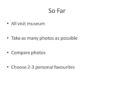
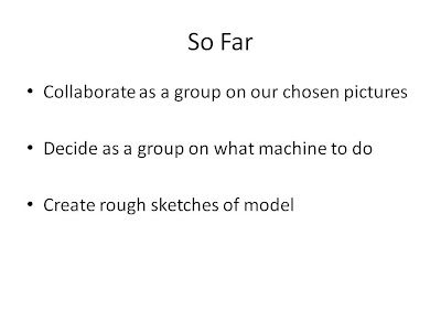
It was important to start by presenting what tasks we had acocmplished over the previous weeks.
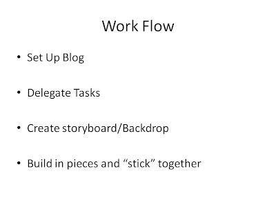
It was then important to present our work flow, and how we were splitting tasks
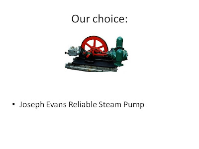
Next we showed the audience what machinary we were modelling, as well as explaining why we came to the decision accompnied with a little information about the machine itself.
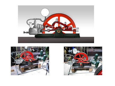
Finally, we showed a few extra images of the machine - Two photographs of the model, and a sketch diagram of the model.
It was essential to create a presentation to allow people to understand how our project was working, both in how we were approaching the design, and also as to how we would be delegating tasks. The slides that were used in the presentation and a summary of each one, and what was mentioned to the audience follow:


It was important to start by presenting what tasks we had acocmplished over the previous weeks.


It was then important to present our work flow, and how we were splitting tasks

Next we showed the audience what machinary we were modelling, as well as explaining why we came to the decision accompnied with a little information about the machine itself.

Finally, we showed a few extra images of the machine - Two photographs of the model, and a sketch diagram of the model.
Wednesday, 21 October 2009
Creating My Head - Conclusions
Over the past five weeks I have been following an online tutorial created by CG artist Eric Maslowski.
The tutorial started out simple enough, and even as it got a little more complicated it seemed easy to follow, however, from the fourth tutorial or so onwards it became a lot more complicated and a lot more unclear.
My first major problem with the tutorial would be that it is hard to understand the narrators accent. This meant that I had to replay many parts of the tutorial, and at some points I still could not understand the narration.
The next problem was that the narrator skipped several parts, or in some parts would run through them so quickly that I could not grasp what was going on.
The final problem I have with the tutorial itself is that it was using an older version of 3Dsmax and when he used certain features, I had to spend time working out what it had been renamed to or where it had been relocated to.
The tutorial however, did show me how to make a head, and I followed the instructions to the best of my ability. From my previous experiences, modelling with 3Dsmax has never been my strongest skill and this was shown in this exercise.
My face started showing problems around the third tutorial when it became apparent that I had added too many quadrants. This caused me problems in the next set of tutorials when I began drawing them out to create my face as I created many triangles and points in this process.
Whilst a face was visible, the problems remained and these got worse as I added the back of the head, where I had again too many quadrants. After adding the ear, it was apparent that I had modelled a head, though it did not look as realistic as possible and had many jagged edges.
In the final stages of the tutorial I had problems editing the UVW map,and had to apply a material rather than a photo as the texture to the face. I was also unable to use any smoothing modifier because of the errors previously.
If I was to restart the tutorial from the beginning, then I would defiantly change my working methods, spending much more time on each section, and then reviewing the tutorial once again after completing each section to ensure that I have made no mistakes.
Overall, I am not best pleased with my end result as I know that with a little more time and care I could have created a head that looks more realistic.
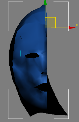
My completed head
After a little work with the material editor, I have finished my head. Notably, two major features are missing from my final model. The most noticeable one is the lack of any smoothing modifier. This is because I received undesirable effects when using Turbo Smooth, or even a Mesh Smooth. The reasons behind this I believe are because the head still has triangles and/or because it contains quadrants with vertex's that are not in the correct position. As I had previosuly attempted to fix this problem, and have once again attempted to, I have no longer got the time to repair or replace the features that are wrong.
I have also added some eyes and a basic lip to the head, as neither of these were mentioned (to my knowledge) in the tutorial.
The materials I applied are a texture for the eyes made in photoshop, and for the skin I have applied a basic Oren-Nayer-Blinn with a flesh colour to the face, which gives the basic impression of skin. I additionally used the same filter but with a more reddish tint to create the lips.
My face appears in the screenshots below, and as described by several people looks like "michael myers" from the Halloween films. As you will also see from when I rendered it, new problems appear which are not visible before rendering, and the face has a very rectangular shape.

 I will review my learning process, the tutorial and my final product in the next entry.
Sunday, 18 October 2009
When things go wrong Pt. 2
After tidying up my face to the best of my abilities, I then moved on to next tutorial, which was titled "Unwrapping UVs for Organic Models".
This tutorial shows you how to use a process titled "Unwrap UVW".
It started off with some rather simple techniques, which involved selecting all the faces minus the ear, and changing their UVW map parameters. For the first set of faces, this involved changing them to to cylindrical, and the axis to X.
You then clicked the edit button beneath paramaters, and this brought up a window with the UV map in it.
This was where I hit my first major problem. The map did not look anything like the one being shown to me in the video, and was rather squashed.
I was able to follow the tutorial onwards however, and I did manage to adjust the faces that over lapped. This tutorial then ended and I carried on to part 2.
Part 2 was the stage where everything went categorically wrong. Selecting the ear, and repeating a similar process to above, I could not get the ear to display correctly, or at the right angle. Because of this, it was impossible to follow the tutorial as it talked about the ear and how to mesh it etc. Skipping this step, I then reached another problem at the next stage.
The next stage required me to use a function of the UVW map editor titled "select inverted faces". This function was completely unavaliable for me at this stage, and remained this way throughout my final attempts at the tutorial.
The tutorial then wanted me to mirror my face on the UVW map in order to get it to cover both faces, however, several attempts at doing this all ended in failure, as my faces UVW map does not appear correctly in the editor, no matter how many times I reattempt this tutorial.
The screenshot below illustrates my problem:

 The following tutorial requires you to export a UVW map into Photoshop, in order to edit it further and to add a photo realistic texture to it. However, because of my above problems, I will unfortunatly be unable to continue with the tutorial past this stage as it is no longer possible to follow.
My solution to finishing the head will be to add a simple texture using the material editor. This won't result in a photo realistic head, but it will result in a head which hopefully resembles a head.
Friday, 16 October 2009
When things go wrong Pt. 1
After completing the ear and attaching it, all the physical features of the head had now been added. At this stage, I took a break away from the tutorials to look at what my head looked like.


As you can see, there are several problems.
Firstly, the face is very lumpy and has patches where the faces should be outwards, and they are facing inwards. Additionally, there's very little nose and the lips are missing.
The side of the head is very blocky and on the rear of the head, there is a split. Also, as shown previosuly the ear is not as good as it could be.
After discussing with several people, including my lecturer what would be the best way of continuing from here, the idea was to attempt to adjust as much as I can, but to also press on and just get as far as I can with the tutorial.
To begin fixing my face, I zoomed in and had a look for any dead end lines, and for any triangles that shouldn't be appearing.


As you can see, these two examples show some of the reasons why the face is not as smooth as it should be. By removing these unrequired quadrants and triangles, or by using the cut tool to extend them out into full continuous lines, I was able to make the face appear smoother. Its also worthe noticing that there was a lot of useless vertex's. These unconnected dots cause massive problems for the faces shape, unless deleted.
Removing as many of these problems as I could helped make my face look smoother.
To solve the next issue of the split, I simply zoomed in on the split and noticed the following:

The split is being caused by the edge being away from the line of symmetry. To solve this problem, I simply moved the edge to the line of symmetry.
The last major problem besides the ears, which are too complex to be fixed without recreating them, thus taking several hours which I don't have to do this head, was the sides of the head looking too blocky.
Whilst turbo smooth does make the head look more round, it struggled to make the sides look smooth, so I had to attempt to work a fix to make it more smooth.
To do this, I removed vertex's, simplified it and also moved vertex's to try and get them in the right position. At this stage, I also took time to modify the nose, in an attempt to define it more. This was achieved by moving vertex's around.
After these lengthy fixes, my head now looked like as follows:
 I am now ready to move onto the next tutorial.
Thursday, 15 October 2009
Creating the Ear
The ear is possibly the most complex part that I have come across in creating the head. Making sure I kept all quadrants relative to my guide pictures was complex, however they now seem much easier after creating the ear.
To begin the lengthy process of creating an ear, we firstly returned to the guideline pictures in Photoshop.
Here, the first task was to draw feature lines once again in blue onto the major features of the ear. This included the ear canal, the ear lobe and certain sections of the inner ear.
The next step was to draw on the quadrants. This was similar to the work I did previously, however this time, I had to ensure that I didn't draw too many as this would over complicate the ear.
After I had finished drawing the lines, I returned to 3Dsmax, where the lines I had drawn appeared on my guideline pictures. Next, I drew lines over my quads, exactly the same as I had done with the face.
Once this was done, I joined the quads together, and then began the process of dragging out the points along the x-axis.
Once this was done, it was possible to see the shape of the ear. At this stage the ear still looked rather rough and there was no backing to it.
It was important to adjust the positioning of the ears quadrants to give it depth and shape.
The tutorial then guided me on how to make the back of the ear look correct. However, this was the first stage in which I felt the tutorial was completely impossible to understand, and I struggled to follow the instructions. Because of this, my ear has very little backing to it, and in the places where there is backing it has affected the front of the ear immensely.
After this, I attached the ear to the side of the head and this stage in the tutorial was completed. As can be seen from the screenshots below, the ear is not perfect, but is identifiable as an ear.


Monday, 12 October 2009
Back of the head
The next stage in the tutorial involved creating the rest of the head, including the neck.
The first task, was to simply create a sphere. this sphere had to be of similar size to the face, and it needed to have both poles on the x-axis.
Once this was created, using the scale tool, I scaled the sphere to make it less round and more head shaped.
After this, I needed to remove faces from it. To do this, I first switched to the left viewport, and then changed the rectangular selection tool to paint selection. Then, holding down the ctrl key, I dragged over the regions I did not need, notably the central area (around the pole) and any area covered by the face. Usefully, the paint selection option automatically duplicates all selections on the opposite side, so this helped me save time. After selecting the regions I needed, I deleted the faces I had previously selected.
The next step was to deleted the right side of the sphere now, as it would no longer be needed, because I would be using the symetry tool again later to duplicate the left side. This once again is to save time.
The next step is to match up the face from the top front of the sphere, to the quadrants on my face. Using the soft selection tool found under the modify menu, I was able to align up the faces.
Once I had matched up the faces, I then needed to clone the faces on the rear of the head, aligning them with the quadrants I had previously drawn, and snapping them to the front of my head.
This stage took several attempts for me to get it to work right, and I still feel that my results look a little "blocky".
The next stage was to increase this down further to create a neck and shoulder area, however I could not follow any guide as my photos did not include both a shoulder area, or much of a neck (mainly because in my photo I was wearing a collared shirt, verus a t-shirt).
After I had created and tidied up the side of the head, I then had to once again use the symmetry tool to create the opposite side of the head. My results after tidying the side up are shown below:

Friday, 9 October 2009
The other side.
The next step after creating the face was to make the right hand side of the face.
The next stage of the tutorial showed me how to acomplish this. It was a rather simple process, and whilst the tiutorial showed me the variety of methods, such as simply copying the entire left side and flipping it so that it could be matched up - an advantage to this method being that it could allow for the face to by symmetrical, however, the disadvantages of this method include not replicating any changes made in the left side, and also the more time consuming process of measuring it up.
The best method recommended by the tutorial was to use the "symetery" function. This was very simple to use, and required me to select the left half of the face, click on the modifier panel, and then choose "Symetry" and then the following options: Flip, X axis and Weld Seam. I then simply had to move my line of symetry slightly, and I had a perfect flip of my face.
Below is a before and after screen grab of my face.:
Before:
 After:

As you can now see I have a full front face, and now I can move on to the next stage, which involves making the back of the head and the neck.
The next stage of the tutorial showed me how to acomplish this. It was a rather simple process, and whilst the tiutorial showed me the variety of methods, such as simply copying the entire left side and flipping it so that it could be matched up - an advantage to this method being that it could allow for the face to by symmetrical, however, the disadvantages of this method include not replicating any changes made in the left side, and also the more time consuming process of measuring it up.
The best method recommended by the tutorial was to use the "symetery" function. This was very simple to use, and required me to select the left half of the face, click on the modifier panel, and then choose "Symetry" and then the following options: Flip, X axis and Weld Seam. I then simply had to move my line of symetry slightly, and I had a perfect flip of my face.
Below is a before and after screen grab of my face.:
Before:
 After:
As you can now see I have a full front face, and now I can move on to the next stage, which involves making the back of the head and the neck.
Wednesday, 7 October 2009
Creating the face in 3D
After the previous task of drawing red boxes onto my face (quadrants), it was now time to make use of them in 3DsMax.
Firstly, I started by drawing over each quadrant using the line tool, which is found in the shape section of the programme.
The lines remain straight so it was important that I uncheck the beizier option and also made sure that I toggled the snap to grid option.
Once I had done this, using the pen tool I sketched over each and every quadrant making sure to match them as closely as possible where it was not possible I made sure that it was within pixels of where it should have been.
After this I then chose one top quadrant, which I then turned into a polygon that created a single shape - It was now important to create all the other shapes, and to do this I clicked on the shape that I just created, and then on the right-hand side, underneath editable polygon, I chose the weld tool. This attached all the other quadrants.
The next stage, was to extrude quadrants on the profile side, giving the face depth of structure .
To do this I had to select all of the lines which ended at the edge of the face. However my first attempt at doing this was not a successful, one and none of the quadrants extruded correctly. This left me with a very messy outline shape which could not be fixed. Therefore I had to go back and repeat the stage where I drew all the quadrants onto my face.
The second time around this was successful and following the tutorial, I continued to drag out the lines, ensuring to make space for the eyes and nose and mouth. Eventually I was left with a grid which was similar to my first grid.
The results can be seen below and as you can see, unfortunately the nose has not come across as well as it should.
What you can notice about the nose is that whilst it is visibly there it isn't very accurate. this is my first major problem with the face, and whilst I am aware that I could return to the beginning stages and correct this I do not have enough time to be able to do this.
Therefore I will continue to work around this problem, as much as I can. Hopefully the final model will not show the problem with the nose as much. It is a shame that I have to leave it like this, but some nose, is better than no nose.
The screenshots from my work are shown below:


Monday, 5 October 2009
Notes from meeting -- 5th October
Minutes from meeting
- We arranged a group meeting for Monday October 5th at 10 AM
- All group members attended this meeting
- We discussed what we believe would be the best way to approach the task in hand
- We discussed what pictures we liked from the collection that we had taken
- We discussed what we could do for each picture that we liked and then narrowed it down working out whether it would be too much work, too little work, or just not within our knowledge of 3dsMax
- We also discussed how best to share work among each other, decision to use Dropbox was made
- Another visit to the museum was discussed, and the time allowing we will hopefully revisit
- The machine that we decided we would most likely be modelling is the "reliable steam engine"
Thursday, 1 October 2009
Preparing photographs, mapping and topology for 3dsMax
The first stage after the lecture was to re-watch the tutorials.
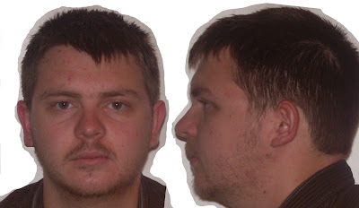
After which it was time to take photographs. I did take photos in the lecture however they did not come out as expected therefore had to retake them when I got home. As you can see below, the photos I took are more than suitable for the task.
With these photos, I took them into Photoshop and then had to adjust them to make them symmetrical.
It is common knowledge that the human face is not symmetrical. Therefore in most cases adjustment will be necessary to align features such as ears, mouth and the eyes.
My case was no different, and I found that no matter what angle I moved the picture to or how much I played with the photo in lens correction there was always a one ear bigger than the other.
This meant that using a pen tablet I had to carefully sketch around my ear using the lasso tool, cut it to a new layer and re size the ear. I then had to use the clone Stamp tool to make it merge into the background.
After I had done this I went back to the lens correction mode and adjusted the angle slightly -- besides this there was not too much editing of the initial image.
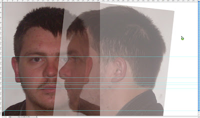
I then imported the second image which is a profile view of my face and then aligned it alongside my other face image.
This required the use of the guidelines built into Photoshop. I then used the transform tool to make sure that it aligned fully.
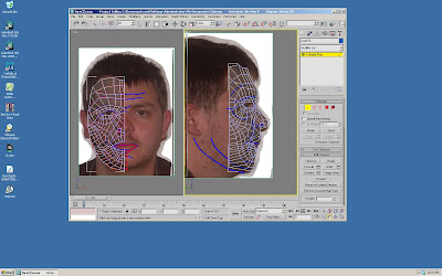
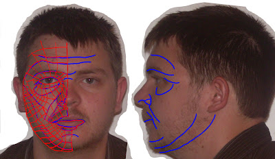
I then moved onto the next stage, which was to draw lines where are features in my face e.g. the crow's feet and the cheekbone. I did this in a new layer using a blue colour and a stage took quite a while because it's important to get the lines in the right place.
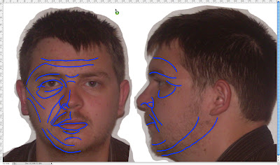
Once I had done this to the first image I moved onto the side image where I didn't have to draw as many blue lines but still needed to draw some.
After this I moved onto the most time-consuming part of this task, which was to map out the topology. This involved drawing red quadrants between the blue lines. it was important not to make any triangular shapes as these would cause problems later on in 3DSMax. The quadrants did not have to be drawn on the profile view.
.jpg)
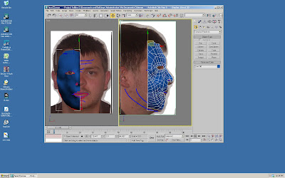
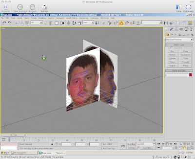
After this, I then had to move the image to 3dsmax. This involves creating a plane, choosing the image as the material. On import the image was scaled incorrectly. However it was possible to go into the features menu, and to turn on UVW mapping and then to press the fit bitmap option. This aligned the bitmap up correctly and then using the gizmo function, I was able to centre the image on my plane.
After doing this, I then needed to go back into the material editor and make the plane self illuminating -- this is so that it can be viewed from all angles and is not dependent on a light source.
After doing this I then had to clone the plane, and rotate it 90°. This gave me the image which you can see below. Finally, I had to align the bitmap correctly on this new duplicate object.
This is where the tutorial has finished for this week.
After which it was time to take photographs. I did take photos in the lecture however they did not come out as expected therefore had to retake them when I got home. As you can see below, the photos I took are more than suitable for the task.
With these photos, I took them into Photoshop and then had to adjust them to make them symmetrical.

It is common knowledge that the human face is not symmetrical. Therefore in most cases adjustment will be necessary to align features such as ears, mouth and the eyes.
My case was no different, and I found that no matter what angle I moved the picture to or how much I played with the photo in lens correction there was always a one ear bigger than the other.
This meant that using a pen tablet I had to carefully sketch around my ear using the lasso tool, cut it to a new layer and re size the ear. I then had to use the clone Stamp tool to make it merge into the background.
After I had done this I went back to the lens correction mode and adjusted the angle slightly -- besides this there was not too much editing of the initial image.
I then imported the second image which is a profile view of my face and then aligned it alongside my other face image.
This required the use of the guidelines built into Photoshop. I then used the transform tool to make sure that it aligned fully.

I then moved onto the next stage, which was to draw lines where are features in my face e.g. the crow's feet and the cheekbone. I did this in a new layer using a blue colour and a stage took quite a while because it's important to get the lines in the right place.

Once I had done this to the first image I moved onto the side image where I didn't have to draw as many blue lines but still needed to draw some.
After this I moved onto the most time-consuming part of this task, which was to map out the topology. This involved drawing red quadrants between the blue lines. it was important not to make any triangular shapes as these would cause problems later on in 3DSMax. The quadrants did not have to be drawn on the profile view.
.jpg)
After this, I then had to move the image to 3dsmax. This involves creating a plane, choosing the image as the material. On import the image was scaled incorrectly. However it was possible to go into the features menu, and to turn on UVW mapping and then to press the fit bitmap option. This aligned the bitmap up correctly and then using the gizmo function, I was able to centre the image on my plane.
After doing this, I then needed to go back into the material editor and make the plane self illuminating -- this is so that it can be viewed from all angles and is not dependent on a light source.
After doing this I then had to clone the plane, and rotate it 90°. This gave me the image which you can see below. Finally, I had to align the bitmap correctly on this new duplicate object.
This is where the tutorial has finished for this week.

Wednesday, 30 September 2009
My visit to the Museum of Power
Today I visited the Museum of power.
This is located just outside of Maldon in Essex, and I was very fortunate that I was able to get up there so easily -- as its location is a little "off the beaten track".
The museum itself is located inside a disused water works building and consists of two rooms and an attachment area.
The main feature of the museum is at a water pump. This huge feature was not operating when I visited though it is apparently operated on certain days. The rest of the museum was given to a collection or displays some which felt relevant to "power" and some which did not.
For example, there were exhibits such as water pumps, oil pumps, steam engines, oil engines but there were also exhibits such as a telephone exchange and a collection of cameras.
My opinion on the museum was that it felt old, poorly maintained, and overall not the most exciting place to visit. it fell heavily orientated towards people who have an interest in engineering whereas it should aim towards both those with an interest those without an interest.
I took a selection of photos there, and was at the museum of approximately 35-45 minutes -- mainly because there were not too many exhibits and also because the smell of oil and diesel became overpowering.
Below is a link to an online gallery containing the photos:
https://vstuff.virginmedia.com/n/50-17/share/LNK61074ac50dbc33d90/
Saturday, 26 September 2009
An introduction to Virtual Environments
This unit has been split into two tasks, with one requiring a lot more work and time than the other, however the other containing some very complex use of 3dsMax.
My initial thoughts on these tasks were that the amount of work required seems overwhelming, however, on further reflection during the tutorial and lecture, it became more apparent that with a well planned schedule, the workload should never be too intense.
The first task is to create a 3d model of my face. This requires taking a photograph of my face and then making sure that it is correctly aligned, and that it is made symmetrical so that when it is taken into 3dsMax, that it will be possible to make a 3d model from the picture.
This work will evolve over the next few weeks, following a series of web based tutorials, guiding me in every step through to even animating my face.
The second task is to create a 3d model for use in a display at The Museum Of Power (located in Maldon, Essex).
This task will be undertaken in a group of four people, and tasks will need to be delegated among each other fairly.
This work will be more time consuming, and it needs to be done to a professional level, as it will be shown to the museum volunteers, and the best groups work will be chosen by them, potentially for display.
My overall thoughts abut this module is that it could be a good learning experience for me, although a lot of work.
Subscribe to:
Comments (Atom)