As the project has now been completed, and a presentation prepared, an it is now a good place to sum up the experience.
The groups were assigned in week 1 after which minimal progress was made due to the creation of a 3d head. In this period of time a visit was made to the museum of power, and a short group meeting was arranged to decided from which of the models we should look into taking further.
The model was chosen, and research into it was made over the next few weeks. Once the 3d head had been created, all work switched to the model.
Within the group, we all found that we had different areas of expertise. In my case, I was best at animation, cameras, lighting, and as the member with the newest version of the software and the most power (64-Bit) rendering.
In agreement with the rest of the group we all worked on different areas, which in my situation, I worked on the wheel to go onto the model, followed by animating the model, adding in lights, and then finally rendering it.
Further tasks in addition to this set also included a further low key spinning version of the model, and also part of the final presentation.
During the work on this project I learned several new skills, firstly, how effective group work can be, when everyone knows their strengths and weakness. Also, i picked up several new skills regarding how to build models using proboolean effectivly, and in animation, with my extensive use of the curve editor tool with the animation.
As the group worked so effectively, we were left with plenty of time to render, which is why a 14 hour render did not cause any problems with our time scale. This gave us plenty of time to add in a narration track, and to edit the video footage in Premiere to make sure we had the files which we needed.
Later on small problems with the animations timing were discovered, and whilst it would be possible to fix the issue, because of its minor importance and low visibility as well as then extensive rendering time, it was decided that there would not be enough time or reason to go back almost 3 weeks to fix such a small issue.
Overall, I am pleased with both the work that we have outputted as a group with this project, and also I am pleased with the input to the model that I had, and that I learned new skills.
Monday, 7 December 2009
Wednesday, 2 December 2009
Another Render.
After creating the final product, a group decision was made that in order to make the presentation of the product to the client more enjoyable; that a untextured rotating un-animated version of the model needed to be created.
The meant opening a previous version, and then removing any animation from it in order to create a greyed out un-animated model.
To make the model rotate, once again, the curve editor was used. In this situation, the model was grouped, and key frames added for it at 0 degrees, 180 degrees and 359 degrees (the 1 degree missing is to avoid a slight delay caused by the same angle being used twice when looping). Then, using the curve editors out of range editor, a simple loop animation was created.
After an initial one frame render, it was decided that the model needed a little mor elighting, so a couple of omni lights were added. The intensity of these lights was too high initially, whoever once they were lowered to 0.4, it was about the right intensity. Shadows were then applied to one light using the advanced shadows setting.
The model was then rendered for 600 frames, giving 20 seconds of animation, which will then be looped for use in the presentation. Unlike the previous render, this version only took 35 minutes.

Monday, 23 November 2009
Lights, Camera, Action.
After combining the animated model with the environment, it was time to add lighting, cameras and to finally render the model. This was the final stage of work done in 3dsMax.
As the model is out in the open within the environment, it was essential that the correct style of lighting was chosen. This was a decision made by all of the group, and an omni light placed in the position of where the sun would usually be was placed.

The next stage was for me to create a camera motion path.
My idea was to creat a camera that moves around the entire environment, panning and zooming in and around the area, which would then allow for editing later on in Premiere to create the final video.
I initially decided on 500 frames of animation, partly due to the amount of time I was expecting the video to take and also because I felt that 500 frames would provide a reasonable amount of camera movements.
However, during the process of moving the camera into various positions, I was unhappy with the speed it moved between areas, and also felt I did not give the camera enough focus on the model itself. I therefore made a decision to increase the frame count to 1000.
The extra 500 frames provided a much better focus on the main parts of the machine, and it worked well, however I felt the need for a slightly longer focus on the top of the machine, so I added an extra 200 frames to allow for this.

After reviewing the camera several times, it was time to render.
Initially, on startup, the estimated time was 8 hours, however during the first few hours this time increased, and it finally settled on a prediction of 14 hours, though the final count was just shy of 13 hours.
Later on, it became apparent that we needed some more close up shots of the machine, and these short sections were rendered in an hour, and lasted for 100 or so frames.
This completed the required 3d work in 3dsMax, and the footage was sent to another member of the group, where it was combined with narration, and cut into a more logical sequence.
As the model is out in the open within the environment, it was essential that the correct style of lighting was chosen. This was a decision made by all of the group, and an omni light placed in the position of where the sun would usually be was placed.

My idea was to creat a camera that moves around the entire environment, panning and zooming in and around the area, which would then allow for editing later on in Premiere to create the final video.
I initially decided on 500 frames of animation, partly due to the amount of time I was expecting the video to take and also because I felt that 500 frames would provide a reasonable amount of camera movements.
However, during the process of moving the camera into various positions, I was unhappy with the speed it moved between areas, and also felt I did not give the camera enough focus on the model itself. I therefore made a decision to increase the frame count to 1000.
The extra 500 frames provided a much better focus on the main parts of the machine, and it worked well, however I felt the need for a slightly longer focus on the top of the machine, so I added an extra 200 frames to allow for this.

After reviewing the camera several times, it was time to render.
Initially, on startup, the estimated time was 8 hours, however during the first few hours this time increased, and it finally settled on a prediction of 14 hours, though the final count was just shy of 13 hours.
Later on, it became apparent that we needed some more close up shots of the machine, and these short sections were rendered in an hour, and lasted for 100 or so frames.
This completed the required 3d work in 3dsMax, and the footage was sent to another member of the group, where it was combined with narration, and cut into a more logical sequence.
Thursday, 19 November 2009
The Animation
After drawing the storyboards it was time to animate the model.
The best process of animation would be to work in areas moving forward from the back - so this meant that I started with the wheel.
My initial plan to animate the wheel was to insert a series of key frames at different rotations. However this process brought about several problems. The first issue was that it was near on impossible to maintain an even rotation. This meant that between key frames the wheel would make it rotate at different speeds - for example between frames 1 and 15 it would rotate 12 degrees, whilst between 15 and 30 it would rotate 15 degrees.
The second major problem with this process was that Max would animate the wheels rotation by moving it in the quickest process. This made it impossible to use the standard keyframe process, and I had to seek an alternative.
The solution to this problem was to use the curve editor. This is a function of which I had no experience with. To use it, I simply create the first part of the animation that I wish to loop, in my case, I create a keyframe of the wheel rotated at 179 degrees. I then right click on the object and chose curve editor.

From the top panel of icons in the curve editor I chose the button named "Parameter Curve Out-Of-Range Types".
This then presented me with another panel asking me what out-of-range type I wanted. The best option for the wheel would be either Loop, or Relative Repeat.

Loop simply repeats my keyframes on a constant basis, whilst Relative Repeat allows for a repeating animation with incremental value.
For this part of the animation Relative Repeat is the best solution.
On choosing this option, visibly nothing appears in the timeline - however once I click play, I can now see the wheel spinning continuously.
The next part of the animation that I needed to animate was the central part.
This part involved a side to side motion with the central component lifting up and rotating during the process.
Before beginning the process of animating this central section, it was important the map out what rotation the component would be at in ech position, as to create a realistic motion.
I started by creating the side to side motion. This was achieved using the loop setting in the out-of-range setting in the curve editor, and three key-frames with the central section position left, centre and right.
The next part to animate was the rotating central component, and to animate this I started by creating keyframes changing the mechanisms rotations, and then I followed this by animating its surrounding components by creating several more keyframes with the component in different positions. Finally, I used the curve editors out-of-range loop setting to make this animation loop.
The final part of the animtion was to animate the front pulleys.
It was decided that this part was the most complex and it was decided to be animated with two members of the group. Whilst the actual animation setup was simple, litterally a case of creating a back and forward motion with a rotation, it involved a lot of components and also required perfect timing. Once again, the curve editor proved useful, and the loop sequence was used again to ensure repetitive motion.
This completed the animation stage, which took several hours, mainly due to the fact that it was essential to line everything up correctly as well as time everything right.
The next stage was for another group member to add textures, bump maps and to then place it into the environment. From there, it was up to me to create some camera angles and to render the final product.

Sunday, 15 November 2009
Model Storyboard
For anything animated, a storyboard is the best way to plan how the animation will run. Below is the storyboard showing how the models animation will work:


Thursday, 12 November 2009
Re-inventing the Wheel
The best strategy for creating our model was to start by splitting up the tasks into areas.
The four main areas of the model are: The Environment to surround the machine, the main frame and components, the casing of the machine, and the wheel at the rear of the machine.
I was given the task of creating the wheel. This is a fair load smaller than the other parts of the model (excluding the environment), so an agreement with the group was that I would take a little more than everyone else in the animation part of the model.
To create the wheel, I started by creating a circle. At this stage, I felt that it would be best to create the wheel as a solid cylinder and then to use pro Boolean to removed the inner features, such as the centre and the ridge around the edge. Below is an image illustrating how I will separate my workload.


I then positioned the shape on top of the cylinder and arranged them into a position where there were six triangular shapes.

My solution was to remove the centre of the wheel completely, and then to create the spokes using a hexagon for the centre and then rectangles as the spokes to the edge of the wheel. I created the shapes using the splines tool, and then I extruded them to create the shapes centre.

This process completed the wheel, and I added a simple colour scheme to it, which will stay until we add a material to it.

Friday, 30 October 2009
Initial Presentation
Below is an item which I posted to the group blog:
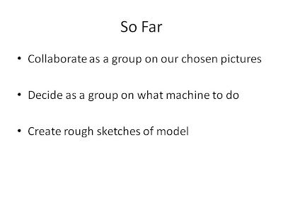
It was essential to create a presentation to allow people to understand how our project was working, both in how we were approaching the design, and also as to how we would be delegating tasks. The slides that were used in the presentation and a summary of each one, and what was mentioned to the audience follow:
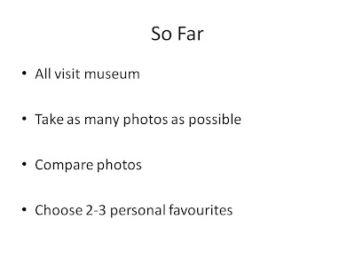
It was important to start by presenting what tasks we had acocmplished over the previous weeks.
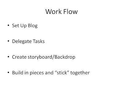
It was then important to present our work flow, and how we were splitting tasks
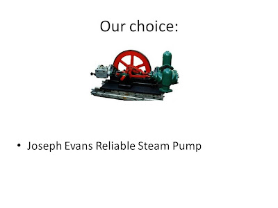
Next we showed the audience what machinary we were modelling, as well as explaining why we came to the decision accompnied with a little information about the machine itself.
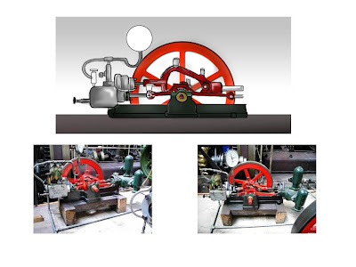
Finally, we showed a few extra images of the machine - Two photographs of the model, and a sketch diagram of the model.
It was essential to create a presentation to allow people to understand how our project was working, both in how we were approaching the design, and also as to how we would be delegating tasks. The slides that were used in the presentation and a summary of each one, and what was mentioned to the audience follow:


It was important to start by presenting what tasks we had acocmplished over the previous weeks.


It was then important to present our work flow, and how we were splitting tasks

Next we showed the audience what machinary we were modelling, as well as explaining why we came to the decision accompnied with a little information about the machine itself.

Finally, we showed a few extra images of the machine - Two photographs of the model, and a sketch diagram of the model.
Subscribe to:
Posts (Atom)